DESIGN EXPLORERIN PROGRESS
RELATIVE SHAFT ANGLEΔθ = 0°
Preliminary concept · Motion exaggerated
01 / Shaft and torsion-bar assembly
01 / Shaft and torsion-bar assembly
A continuous mechanical path.
Input, torsion bar, output.
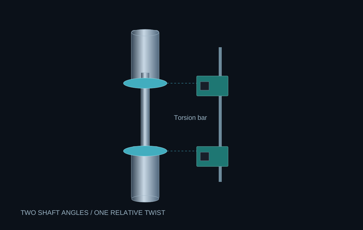
The input shaft connects to the steering wheel; the output shaft continues toward the steering mechanism. A slender torsion bar joins them and deforms elastically under load. The pins and shaft connections shown here follow my preliminary layout sketch.
02 / Two rotating magnets · fixed sensors
Let the magnets turn.
Keep the sensors fixed.
A ring magnet rotates with each shaft. Two separate TMR sensor boards stay on a stationary support alongside the column, each observing its own magnet. Their mounting, alignment, air gaps, and wiring are part of the installed sensing system.
03 / Δθ = θ input − θ output
The difference reveals the effort.
Read relative angle, not just position.
Both shafts can rotate together as the driver steers. Under load, the torsion bar also twists, creating a small difference between their angles. In this illustrative example, 30° at the input and 28° at the output produce 2° of relative twist. The visible deformation is exaggerated for clarity.
04 / Torque estimate → assist logic
From twist to an assist request.
Calibrate before controlling.
With calibrated torsional stiffness kₜ, the controller can estimate driver torque as T = kₜΔθ, using consistent angle units. Angle wrapping, sensor offsets, synchronized sampling, and fault checks matter. Assist logic and a safe disabled-assist response still need implementation and testing.